I. What is a Variable Frequency Drive (AC Drive) (VDF)?
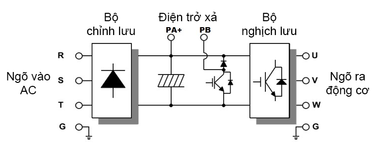
Also known as Inverter.An Inverter is an electrical device that controls the speed and torque of a motor by varying the frequency and voltage supplied to the motor.
The ATV310 Schneider Variable Frequency Drive is suitable for applications involving industrial machinery; the Variable Frequency Drive ATV310 uses a three-phase asynchronous motor ranging from 0.37 kW/0.5 HP to 11 kW/15 HP.
The ATV310 Variable Frequency Drive is designed as a plug-and-play device, compact in size, durable in design, easy to install, and features functions that make it particularly suitable for industrial machine applications and some consumer machines.
The VFD is a reliable and cost-effective solution for Original Equipment Manufacturers (OEMs).
The ATV310 Variable Frequency Drive is developed with guaranteed quality: the components used have a lifespan of up to 10 years.
1. Overview of ATV310 Schneider Variable Frequency Drive
The ATV310 Schneider, part of the EasyLine product series, is an economical solution, suitable for basic applications at an affordable price. This product is designed for 3-phase asynchronous motors with capacity from 0.37 kW to 22 kW.
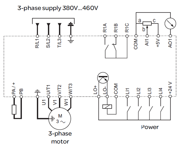
2. Wiring Diagram of ATV310 Variable Frequency Drive
3. Accessories for ATV310 Variable Frequency Drive
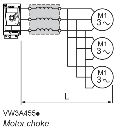
- Using line choke, motor choke, braking resistor.
- Help the Variable Frequency Drive operate stably.
- Help protect the Variable Frequency Drive, enhancing its lifespan.
II. Basic Setting Parameters of ATV310 Variable Frequency Drive
Go to Conf menu -> Full -> 300
+ 301 = 50Hz (Motor type, always set to 50Hz)
+ 302 = Rated motor power (refer to motor label)
+ 304 = Rated motor voltage (refer to motor label)
+ 305 = Rated motor current (refer to motor label)
+ 306 = Rated motor frequency (refer to motor label)
+ 307 = Rated motor speed (refer to motor label)
+ 309 = Motor control type:
00 - Vector rule
03 - U/F rule
06 - Fan/pump rule
Select 309 = 00 for heavy load (conveyor, crusher, press) use vector rule
Select 309 = 03 when motor parameters are not available
Select 309 = 06 if using for fan/pump, use the fan/pump rule. Switch to 00 (vector law) if error occurs. Setting 310=80%, 311=0%
+ 318 = 01 (perform auto-tuning, if successful, it will return “02”)
If the VFD reports a tuning error (F028), retry
If tuning error (F028) persists, set 319 = 01, re-enter motor parameters (enter cos phi – 303), and perform tuning again.
Go to Conf menu
+ 501.0 = VFD acceleration time (s)
+ 501.1 = VFD deceleration time (s)
Go to Conf menu -> Full -> 600
+ 603 = 01 (Select Catch on the fly function)
+ 604 604.0 = Motor thermal current (set overload protection for the motor)
III. Fault Code Table of ATV310 Variable Frequency Drive
Fault Code | Fault Name | Diagnosis | Solution |
F001 | Precharge | • Charging relay control error or damaged charging resistor | • Turn off the device and then turn it back on
• Check the connections
• Check the stability of the main supply
• Contact Schneider Electric
|
F002 | Unknown drive rating | • Power card and the storage card are of different versions | • Contact Schneider Electric |
F003 | Unidentified or incompatible power board | • The power card is not compatible with the control card | • Contact Schneider Electric |
F004 | Internal serial link error | • Interruption of communication between internal cards | • Contact Schneider Electric |
F005 | Invalid industrialization zone | • Internal data inconsistency | • Contact Schneider Electric |
F006 | Current measuring circuit | • Incorrect current measurement due to hardware circuit fault | • Contact Schneider Electric |
---- | Problem with firmware | • Invalid firmware update using Multi-Loader tool | • Re-download firmware |
F007 | Internal thermal sensor detected error | • Device's temperature sensor is operating inaccurately
• The drive is short circuited or open circuited | • Contact Schneider Electric |
F008 | Internal CPU | • Internal micro processor error | • Turn off the device and then turn it back on
• Contact Schneider Electric
|
F009 | Overbraking | • Sudden braking or high inertia overload | • Increase deceleration time • Install a module with a braking resistor if necessary • Check main supply voltage to ensure voltage is acceptably below maximum (20% over maximum main supply during run status)
|
F010 | Overcurrent | • The parameters in the motor control menu are not correct • Inertia or load is too high • Mechanical lock | • Check the parameters
• Check the size of the motor/drive/load
• Check the mechanism state
• Connect the line motor chokes
• Reduce the switching frequency range
• Check the ground connection of the device, motor cable and motor insulation
|
F011 | Device overheating | • Device temperature is too high | • Check motor load, device ventilation and ambient temperature. Wait for the device to cool down before restarting. |
F012 | Overload process | • Overload process | • Check that device parameters and application processes are compatible. |
F013 | Motor overload | • Triggered due to excessive motor current | • Check the configuration of the motor thermal protection and motor load. |
F014 | Loss of 1 output phase | • One phase loss on the drive output | • Check the connections from the drive to the motor. • If using a downstream contactor, ensure the connection, cable and contactor are right. |
F015 | Loss of 3 output phases | • Motor is not connected
• Motor power is too low, less than 6% of the device's rated current
• Output contactor open
• Instability in the motor current | • Check the connections from the drive to the motor.
• Test on low power motor or without motor. In factory setting mode, motor phase loss detection is active
Output phase loss detection 605 = 01. Try testing the device in a test or maintenance environment, without using a motor of the same rating as the device, deactivating the motor phase loss detection. Output phase loss detection 605 = 00.
• Check and optimize IR compensation 310, Rated motor voltage 304 and Rated motor voltage 305 and after that performing auto-tuning 318.
|
F016 | Main overvoltage | • Line voltage is too high:
- When powering on the device, the power supply is 10% above the maximum acceptable level.
- Motor has no run command, 20% above maximum line supply.
• The power supply is disturbed. | • Turn off the device. Check and adjust line voltage.
After the line returns to nominal voltage (within tolerance) turn on the power.
If code F016 appears intermittently, set R1 assignment 205 to 01 and it can be connected to the upstream protection in order to avoid overvoltage in the drive. In this case LO1 can be used for other status.
|
F017 | Input phase loss | • The drive is supplied incorrectly or the fuse is blown.
• One phase failure
• The 3-phase ATV310 is used on a single-phase line supply.
• Unbalanced load
• This protection only works with the device on load. | • Check power connection and fuse.
• Using 3-phase line supply.
• Turn off reporting of this type of error by setting Input Phase loss detection 606 to 00.
|
F018 | Motor short-circuit | • Short circuit or grounding at the device output
• Ground fault while in running status.
• Motor switching while in running status.
• Significant current leakage to ground while some motors are connected in parallel. | • Check the cables connecting the device to the motor and the motor insulation.
• Adjust the switching frequency.
• Connect the chokes in series with motor.
• Adjust the speed loop.
|
F019 | Ground short-circuit | • Short circuit or grounding at the device output
• Ground fault while in running status.
• Motor switching while in running status.
• Significant current leakage to ground while some motors are connected in parallel. | • Check the cables connecting the device to the motor and the motor insulation.
• Adjust the switching frequency.
• Connect the chokes in series with motor.
• Adjust the speed loop. |
F020 | IGBT short-circuit | • Internal power component short circuit detected when power on | • Contact Schneider Electric |
F021 | Load short circuit | • Short circuit at drive output
• Detect short circuit when running command or DC command if parameter IGBT Test 608 is set to 01 | • Check the cable connecting the device to the motor and the condition of motor insulation. |
F022 | Modbus interruption | • Communication interruption on the Modbus network | • Check all connections on the communication bus.
• Check the time-out (Modbus time-out parameter 704).
• Refer to the Modbus user manual. |
F024 | HMI communication | • Interrupted communication with external display terminal | • Check terminal connection. |
F025 | Overspeed | • Instability • Overspeed is related to application inertia | • Check the motor
• If the overspeed is more than 10% higher than the Top frequency 308 adjust this parameter if necessary.
• Add a braking resistor
• Check the size of the motor/device/load.
• Check speed loop parameters (gain and stability)
|
F027 | IGBT overheating | • Device overheated
• IGBT internal temperature is too high compared to ambient temperature and load. | • Check the size of the load/motor/device.
• Reduce Switching frequency 315.
• Wait for the drive to cool down before rebooting. |
F028 | Autotuning error | • Motor is not connected to the drive
• Loss of motor phase
• Special motor
• The motor is rotating | • Check if the motor is compatible
• Check if the motor is in autotuning
• If an output contactor is being used, close it during autotuning
• Check if the motor has stopped completely
|
F029 | Underload process | • Underload process
• The time that the motor current is below the threshold 211 exceeds the Application underload time delay 210 for protection. | • Check if parameters and application processes are compatible. |
F030 | Undervoltage | • Line supply is too low.
• Transient voltage dip | • Check the voltage and parameters on the Undervoltage phase loss menu 607 |
F031 | Incorrect configuration | • The HMI is replaced by an HMI configured on a device for different rating.
• The current configuration of the parameters is incorrect. | • Go back to factory settings or take a configuration backup, if it's valid.
• If the error persists after reverting to factory settings, contact your Schneider Electric representative.
|
F032 | Invalid configuration | • Invalid configuration | • Check the previously loaded configuration.
• Load a compatible configuration.
|
F033 | Loss of AI1 current | Detected if:
• AI1 analog input is configured as current
• Current scaling parameter AI1 of 0% 204.1 is greater than 3 mA
• Analog input current is lower than 2 mA | • Check the terminal connection |
IV. Product Details of the ATV310 Variable Frequency Drive Series
The Schneider ATV310 Variable Frequency Drive is an excellent choice for simple industrial applications due to its cost optimization and operational efficiency. Here are the detailed specifications for this product series:
1. Variable Frequency Drive ATV310H037N4E
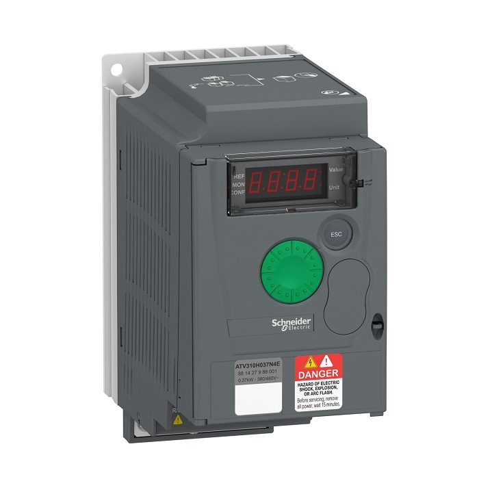
Variable Frequency Drive Schneider ATV310H037N4E Power: 0.37kW, View details here. 2. Variable Frequency Drive ATV310H075N4E
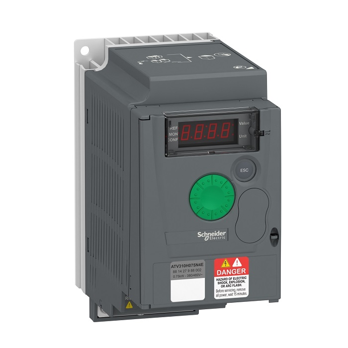
Variable Frequency Drive Schneider ATV310H075N4E Power 0.75kW, View details here 3. Variable Frequency Drive ATV310HU15N4E
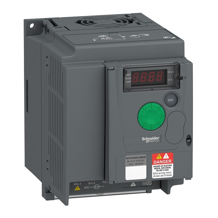
Variable Frequency Drive Schneider ATV310HU15N4E Power 1.5kW, View details here. 4. Variable Frequency Drive ATV310HU22N4E
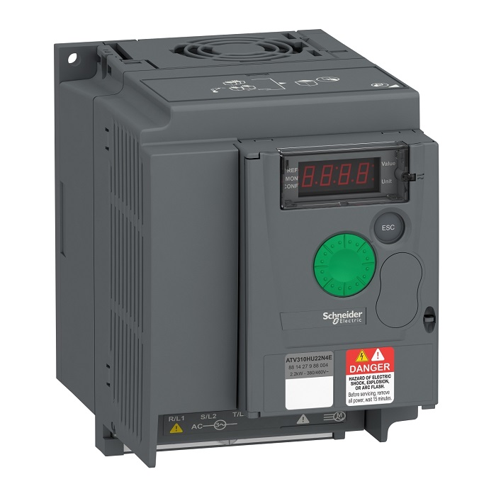
Variable Frequency Drive Schneider ATV310HU22N4E Power 2.2kW, View details here. 5. Variable Frequency Drive ATV310HU30N4E
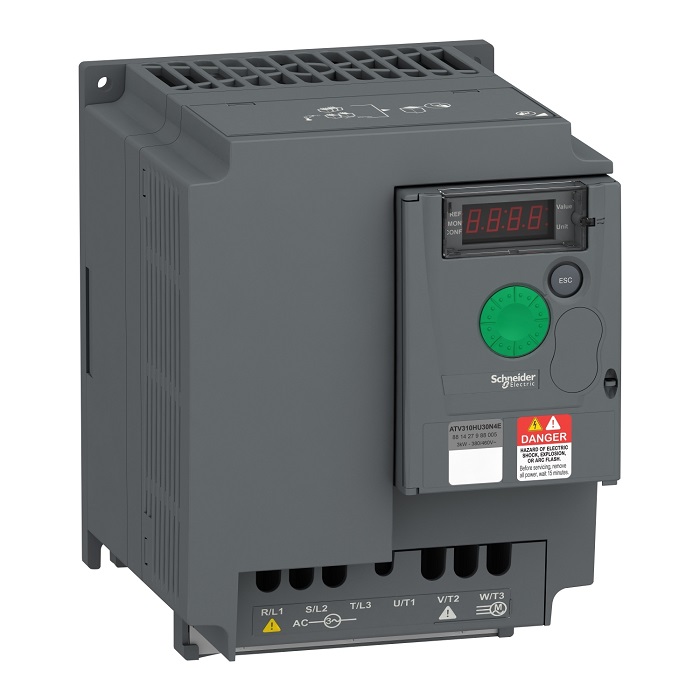
Variable Frequency Drive Schneider ATV310HU30N4E Power 3kW, View details here. 6. Variable Frequency Drive ATV310HU40N4E
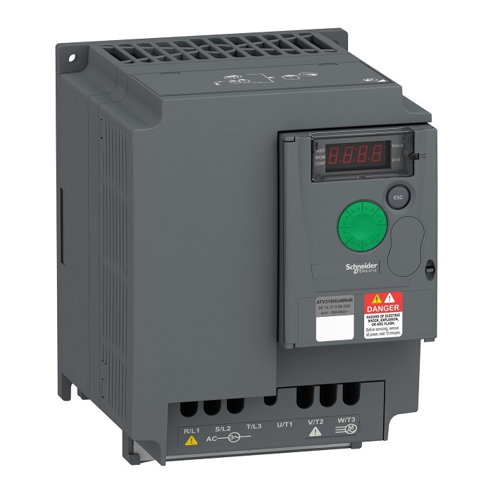
Variable Frequency Drive Schneider ATV310HU40N4E Power 4kW, View details here. 7. Variable Frequency Drive ATV310HU55N4E
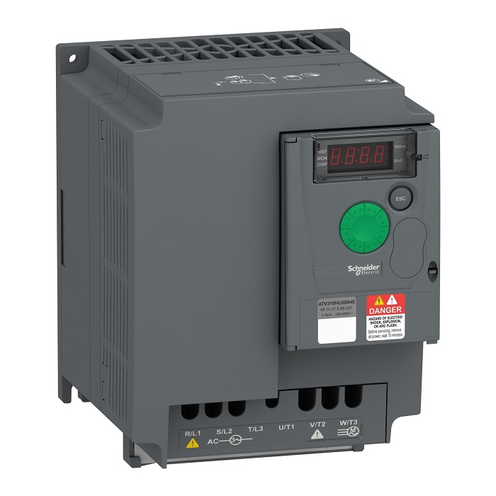
Variable Frequency Drive Schneider ATV310HU55N4E Power 5.5kW, View details here. 8. Variable Frequency Drive ATV310HU75N4E
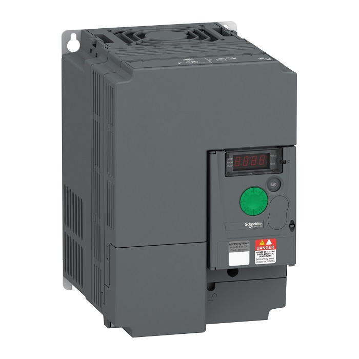
Variable Frequency Drive Schneider ATV310HU75N4E Power 7.5kW, View details here. 9. Variable Frequency Drive ATV310HD11N4E
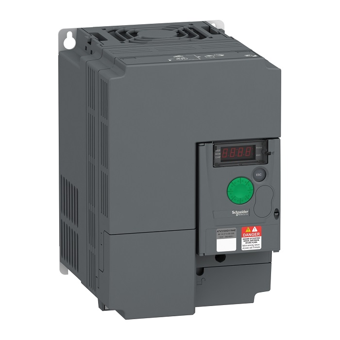
Variable Frequency Drive Schneider ATV310HD11N4E Power 11kW, View details here. 10. Variable Frequency Drive ATV310HD15N4E
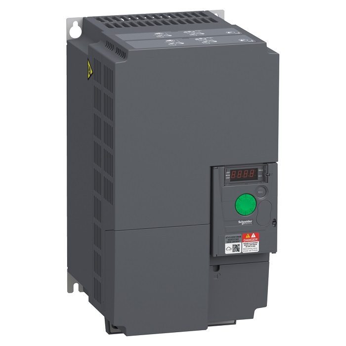
Variable Frequency Drive Schneider ATV310HD15N4E Power 15kW, View details here. 11. Variable Frequency Drive ATV310HD18N4E
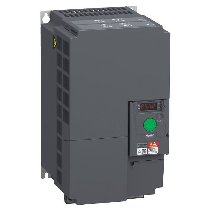
Variable Frequency Drive Schneider ATV310HD18N4E Power 18kW, View details here. 12. Variable Frequency Drive ATV310HD22N4E
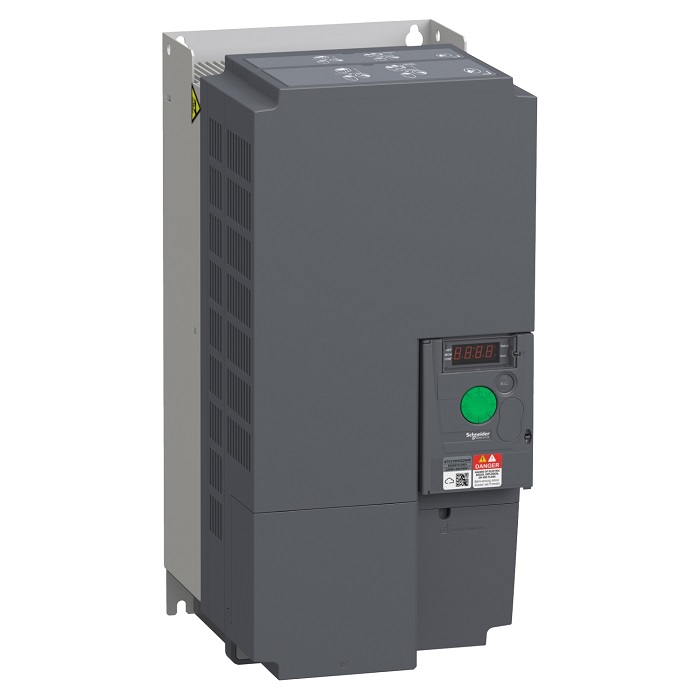
Variable Frequency Drive Schneider ATV310HD22N4E Power 22kW, View details here. V. User Manual of the ATV310 Schneider Variable Frequency Drive:
You can refer to the English User manual of the Schneider ATV310 VFD for more information.
VI. Applications of the ATV310 Schneider Variable Frequency Drive:
The Schneider ATV310 VFD is widely used in various industries such as:
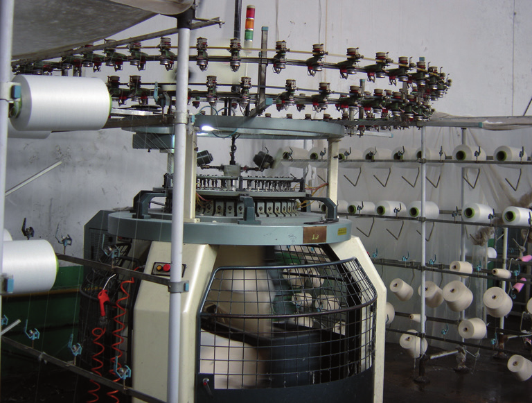
Schneider ATV310 VFD for textile machine
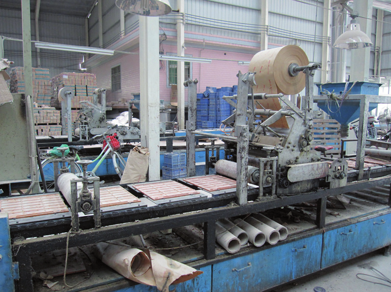
Schneider ATV310 VFD for packaging production machine
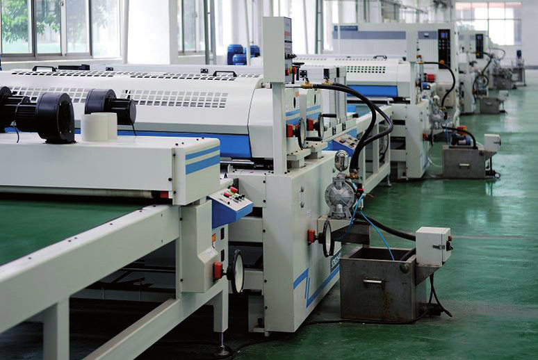
Schneider ATV310 VFD for printing machine
Contact us for more information:
HAN MY VIET AUTOMATION CO., LTDAddress: 203-205 Nguyen Thai Binh St., Nguyen Thai Binh Ward, Dist.1, Ho Chi Minh City, Viet Nam.
Tel: (+8428) 3821 6710 - 3821 6711
Hotline: +84916 216 710
Website: www.hanmyviet.vn + HAN MY VIET Ha Noi Branch
Address: 72 Bui Ngoc Duong St., Bach Mai Ward, Hai Ba Trung Dist., Ha Noi, Viet Nam.
Phone: Ms. Hien +8498 699 1948
+ HAN MY VIET Bac Ninh Branch
Address: 6 Ngoc Han Cong Chua St., Hoa Dinh Quarter, Vo Cuong Ward, Bac Ninh, Viet Nam.
Phone: Mr. Tien +8497 546 0366
+ HAN MY VIET Da Nang Branch
Address: 26 Tang Bat Ho St., Hai Chau II Ward, Hai Chau Dist., Da Nang, Viet Nam.
Phone: Ms Hoa +8433 636 3965
+ District 5, Ho Chi Minh City Branch
Hung Phu Automation Technology Co., Ltd.
Address: 27 Trieu Quang Phuc St., Ward 10, Dist. 5, Ho Chi Minh City, Viet Nam.
Phone: 190 063 3459 – (+8428) 7300 3459
+ Binh Duong Branch
Hung Viet Automation Electric Co., Ltd.
Address: 1/13 Binh Duc 2 Quarter, Binh Hoa Ward, Thuan An City, Binh Duong Province, Viet Nam.
Phone: (+84274) 363 6508 – +8490 310 8416