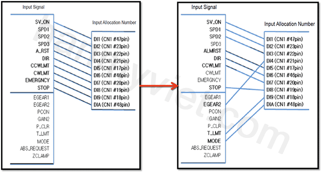
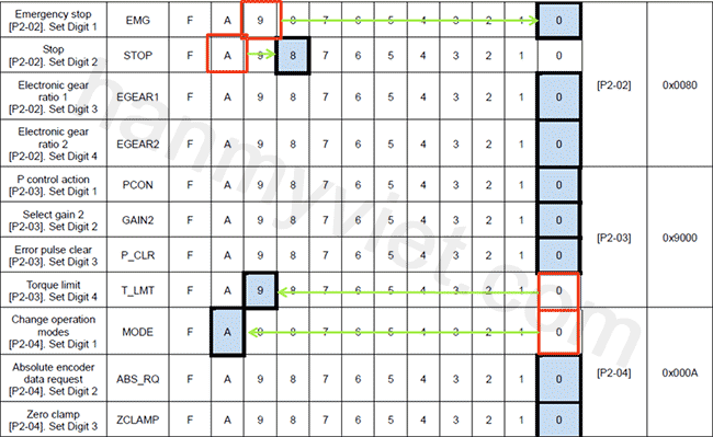
A. DEFINITION OF INPUT SIGNAL
![](http://i793.photobucket.com/albums/yy216/hanmyvietautomation/xgt-servo-1_zpsd420f8f5.png)
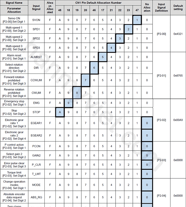
B. EXAMPLE OF INPUT SIGNAL DEFINITION
- Redefine the digital input signal pins as shown in the figure below:
![](http://i793.photobucket.com/albums/yy216/hanmyvietautomation/xgt-servo-2_zps3509ead4.png)
![](http://i793.photobucket.com/albums/yy216/hanmyvietautomation/xgt-servo-3_zpsbb4f553d.png)
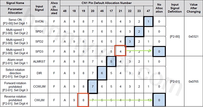
Note: CN1 pins which are not connected are defined as "0".
![](http://i793.photobucket.com/albums/yy216/hanmyvietautomation/xgt-servo-4_zpsc1961656.png)
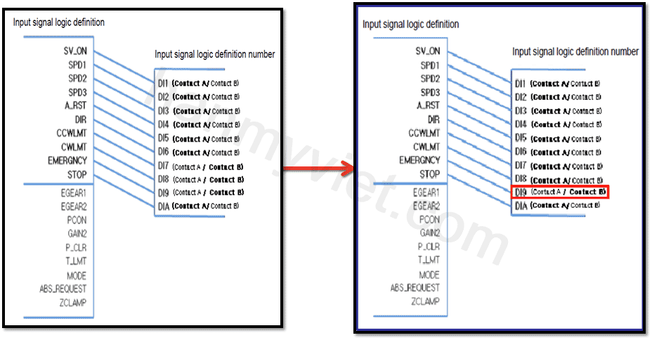
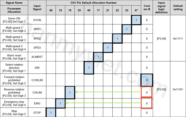
C. LOGICAL DEFINITION OF INPUT SIGNAL
![](http://i793.photobucket.com/albums/yy216/hanmyvietautomation/xgt-servo-5_zps20b0af88.png)
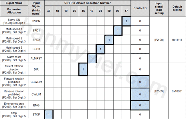
D. EXAMPLE OF INPUT SIGNAL LOGICAL DEFINITION
- The logical definition of the signal input pins as shown in the figure below:
![](http://i793.photobucket.com/albums/yy216/hanmyvietautomation/xgt-servo-6_zps57ed3042.png)
![](http://i793.photobucket.com/albums/yy216/hanmyvietautomation/xgt-servo-7_zps71a18969.png)